
What are a NPN sensor and a PNP sensor like?
Useful knowledge in electrical engineering for mechanical engineers
Related YouTube video
Contents
Are you a mechanical engineer having concerns in NPN and PNP?
You are a mechanical engineer and designing a machine. You need to use some sensors for the machine. You pick up a catalog of sensors to select the sensors you need, and you find these two words, “NPN sensor” and “PNP sensor”.
You have heard of the words and you know that the words are related to “transistors”. However, you don’t know about transistors well. You start checking how transistors work and then you realize that it takes long time to understand how to use transistors… Eventually, you give up understanding what are NPN and PNP.
I’m hoping that this article helps that kind of mechanical engineers easily understand what a NPN sensor and a PNP sensor are like.
After you read this article, you understand how a NPN sensor and a PNP sensor work, and you become able to connect the sensors to a PLC. Even if you don’t have enough knowledge about a PLC, you can understand this article.
What is a NPN sensor and a PNP sensor?
As you can guess, transistors are used in many ways. However, in the case of the sensors in the figure below, it’s okay if we consider one of many usages of transistors, because the sensors are just switches. So, I’m going to tell you about how a transistor works as a switch in this article first.

By the way, the sensors above are not transistors themselves. It’s just that they work as if they were transistors.
Basic knowledge about transistors as a switch
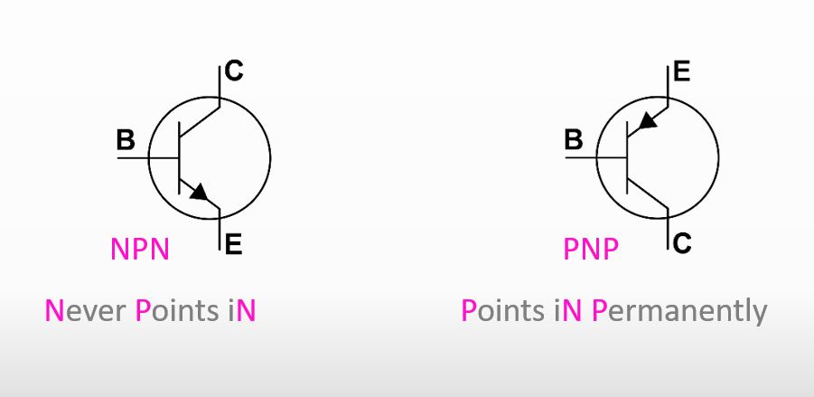
The drawings below are the symbols of a NPN transistor and a PNP transistor. You can easily memorize the symbols if you pay attention to the arrows in the symbols. “Never Points iN” is for NPN. “Points iN Permanently” is for PNP.
How do they work as a switch? Actually, it’s easy. If electric current flows between B and E a little, C and E get connected with each other like the figure below as if there was a jumper wire that connects C and E.
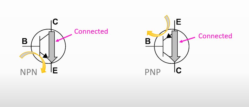
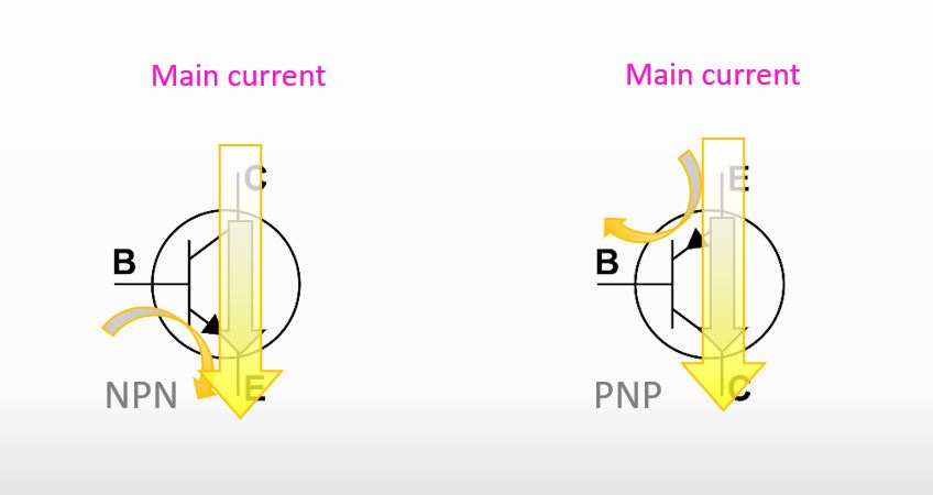
So, electric current can flow between C and E, and actually the current is used as main current.
This is how a transistor works as a switch. You can regard the current flowing between B and E as the button of a switch as seen in the figure below.

How do a NPN sensor and a PNP sensor work in a circuit?
The drawing below specifically shows how a NPN sensor and a PNP sensor are used. I took a photoelectric sensor as an example. If the sensor detects an object, the contact inside the sensor closes. And then the current between B and E flows. As I already introduced, the current triggers the main current to flow. Eventually, the lamp turns on.
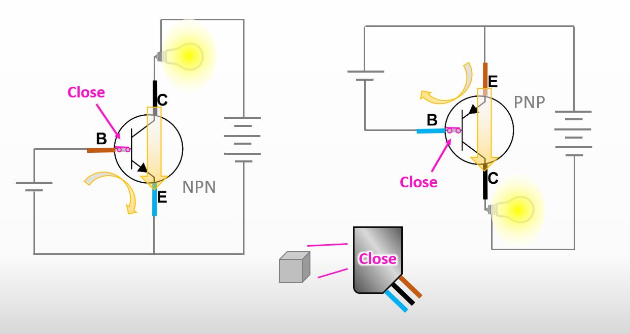
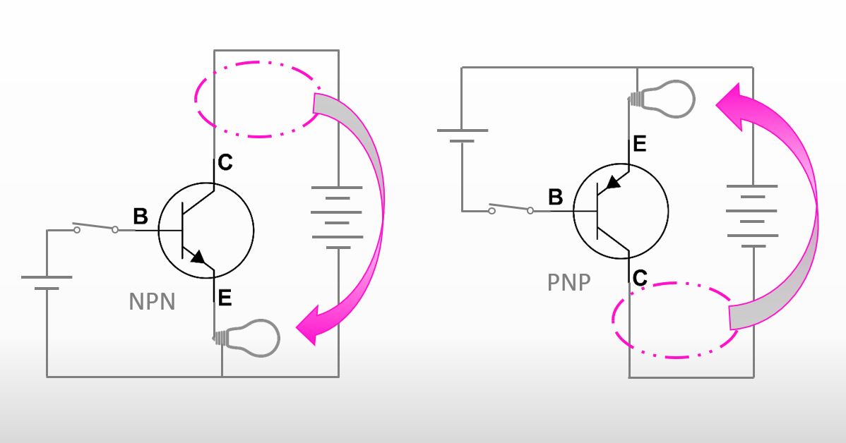
The position of the load (= the miniature light bulb) is important. You might think that it’s okay if you put the load at the opposite side like the drawing below. However, you must not put the load on the E side (emitter side).
I’m not going to go to the details about the reason but to put it simply, it would become troublesome to control the amount of the current between B and E. The amount of the current is important because it controls the amount of the main current. What I’d like to say is that if you put the load on the emitter side, the current between B and E may not flow properly, and which means that the main current between C and E may not flow properly.
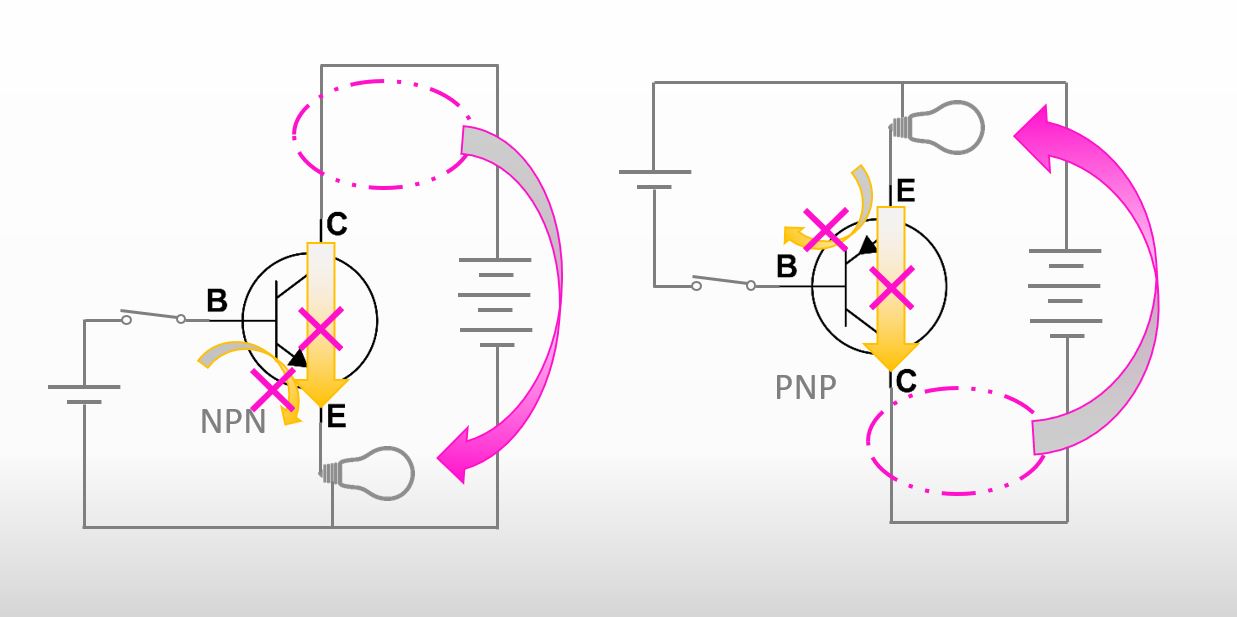
Is it complicated? Please take it easy. The only important thing I’d like you to keep in mind in this article is that “a load is connected to a collector”. Sorry, I forgot to tell you but C stands for a collector.

How can we connect a NPN sensor and a PNP sensor to a PLC?
General drawings of a NPN sensor and a PNP sensor are in the figure below.

How can we connect a sensor to a PLC. Even if you don’t know about a PLC, please don’t be worried. The system is very simple. The purpose of a PLC is to decide output signals based on inputs. For instance, “If electric current flows through No.2 of the PLC, the PLC applies voltage to No.6 of the PLC”. If you do wiring so that an air cylinder works when No.6 of the PLC is applied voltage, you can make this situation happen, “If electric current flows through No.2 of the PLC, the air cylinder works”. We pay attention to only inputs of a PLC in this article. If you do the wiring like below, the PLC notifies the machine that No.2 is ON.
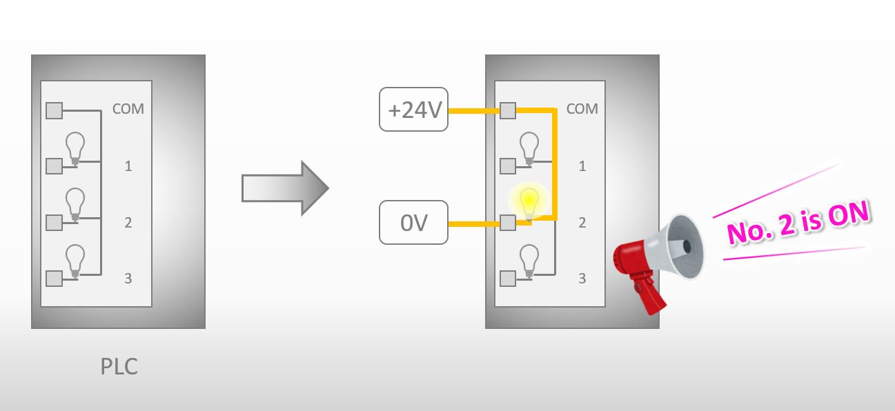
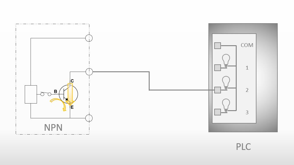
If a sensor detects something, No.2 lamp of the PLC turns ON. How can we make this situation happen? Firstly, let’s think about how we can connect a NPN sensor to the PLC.
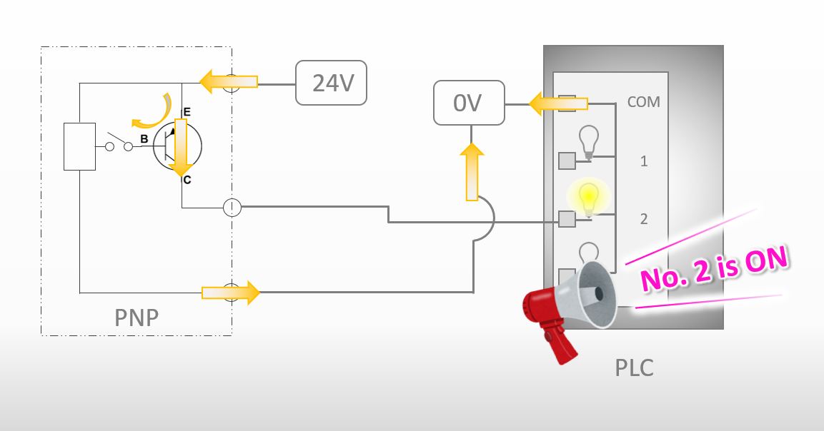
Do you still remember that “a load is connected to a collector”? I connected the load in the PLC to the collector in the sensor in the drawing below.

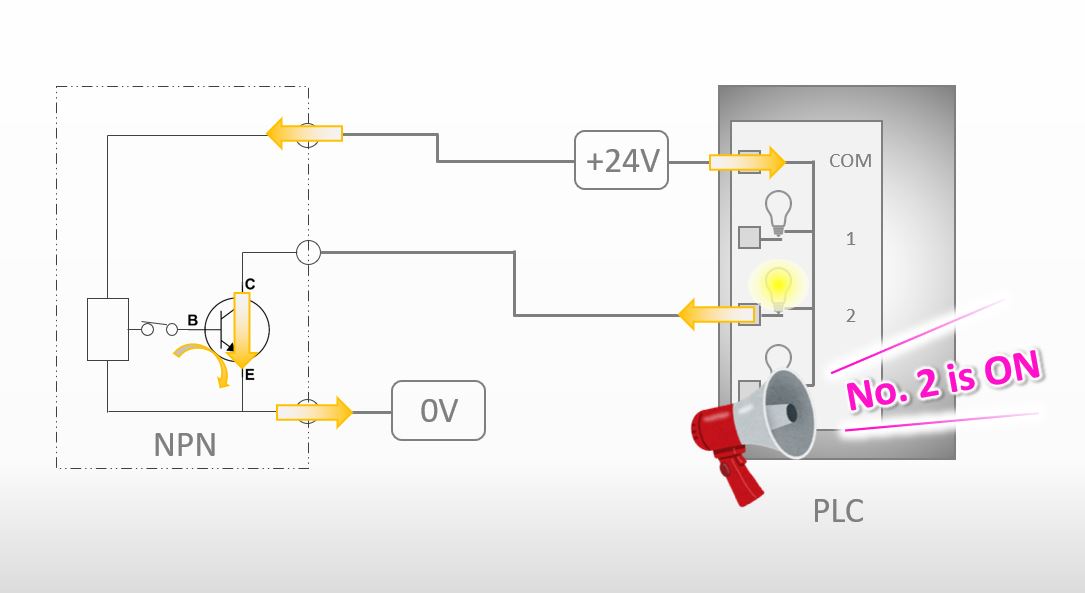
Let’s move on to the next step. Please pay attention the directions of the yellow arrows in the figure below.
In order to make the current flow the directions shown above, we should do the wiring like the figure below. We succeeded in connecting a NPN sensor to a PLC.
How can we connect a PNP sensor to a PLC? The figure below is how we should do the wiring.